Synchronous Protocols
To provide the fast, high integrity communication required by most mainframe computers, HUNTER has a synchronous data communication capability.
Communication takes place using synchronous transmission of data blocks. These blocks are checked using check characters and acknowledged as appropriate using particular protocols.
Currently available as a factory option is the IBM 2780 [1] communication protocol providing the bisynchronous communications. Other protocols are in development.
IBM 2780 On HUNTER
IBM 2780 is used for batch entry by use of “job cards”. HUNTER is easily programmed to simulate the use of job cards providing all the processing facilities normally available on a remote terminal.
HUNTER is the most advanced portable to offer a comprehensive implementation of IBM 2730 in true synchronous mode.
Use of this standard provides access to a wide range of mainframe computer systems, directly and without need for supporting equipment. Data files can be exchanged between HUNTER and mainframe with great flexibility, convenience and dependability.
Technical Implementation
Synchronous transmission using Bisync.
Character set - EBCDIC
Full CRC generation, error handling and flow control.
Modem handshake lines available.
Internal or external clocking options.
May be used over the public switched telephone network or private lines.
Records terminated using the EM character, providing optimum throughput.
The “Wait acknowledge” is fully implemented.
Protocol use is completely transparent to user programs.
Data Rates - up to 9600 Hz with external clocking, up to 1800 Hz using internal clocking
The internal self-synchronising feature enables HUNTER to HUNTER communications over standard 300 baud asynchronous modems.
Synchronous Communication
Synchronous communication transfers data as a continuous stream of data characters, without the need for start and stop bits as used in asynchronous communication. This maximises the data transfer rate for a given channel bandwidth. For the receiver to be able to use the data two levels of synchronisation need to take place:
Bit Synchronisation
Two techniques are used by HUNTER to achieve bit synchronisation.
External Clocking allows both transmit and receive to be synchronised using two independent clocking signals. These signals are generated by either a modem or modem eliminator. The selection ‘CLK’ on the speed selection of transmit or receive menus selects this mode.
Two pins are provided for the clock signals, Pin 15 provides the transmit clock and pin 17 the receive clock.
On transmit, a rising edge (-12V to +12V) causes a bit to change on the transmit output (pin 2). On receive, a falling edge (+12V to -12V) causes the state of the receive input (pin 3) to be sampled.
Warning
It is important that maximum clock speed on HUNTER should not exceed 9600 Hz (giving a data rate of 9600 baud). The minimum speed is approximately 100Hz. Exceeding this clock rate may cause unpredictable results.
Alternatively, HUNTER can self clock. This is achieved by selecting from the menu the desired transmit and receive baud rates in the range 50-4800 baud, as for asynchronous. On transmit, the data is sent out by using internal timing, with no reference to any external clock source.
To receive incoming data HUNTER times from rising edges (-12V to +12V) on the receive data line to give internal clocking.
Self clocking is useful for HUNTER - HUNTER communications. It may be used over asynchronous modems to provide both increased throughput and data integrity.
Character Synchronisation
To be able to extract eight bit data characters, HUNTER has to synchronise itself to the incoming characters correctly. This is done by detecting special synchronising characters called SYN characters (32H). HUNTER considers synchronisation to have been achieved after receiving two contiguous SYN characters.
After receiving the two synchronising characters each group of eight received bits are then considered to be a character.
Synchronisation is considered to have been lost if a line turnaround character is received (CFFH). This is equivalent to an open line.
Prior to sending the synchronising characters, HUNTER transmits an 0AAH pad character which is to assist in bit synchronisation.
Every data block whether it consists of one or 500 characters, must start with a pad character, and two SYN characters and terminate with line turnaround.
Binary Synchronous Communications (BSC)
The information carrier for 2780 is the binary synchronous communications (BSC) procedure. The character set used is EBCDIC (Extended Binary Coded Decimal Interchange Code). The following is a description of the subset of BSC used for HUNTER 2780 emulation.
Note
HUNTER generally operates using the USACII (United States of America Standard Code for Information Interchange). Characters either transmitted or received by Basic will be in ASCII, so CHR$, LOPCHR, etc., instructions all generate ASCII characters. To use EBCDIC the 2780 driver software utilises an ASCII to EBCDIC and EBCDIC to ASCII code converter. The conversions used are listed in section ASCII to EBCDIC Conversion. The code used on the transmission channel is transparent to Basic programs, and need not concern the programmer.
Text Blocking
BSC defines general structural procedures for the blocking of information. Several control characters are used for the control of message blocks.
A message consists of one or more blocks of text data. The start of text character (STX) is used immediately preceding each block of data. Each data block but the last is terminated by an end of transmission block (ETB) character or an intermediate text block (ITB) character. The last data block ends with an end of text (ETX) character.
Error Checking
Each block of data is error checked by the receiver by a cyclic redundancy check (CRC). After each transmission the receiver normally replies with ACK0 or ACK1 - data accepted continue sending; of with NAK - data not accepted (e.g. due to a data transmission error), retransmit the previous block.
CRC-16
HUNTER uses the accepted error checking method of the cyclic EBCDIC 2780. The redundancy check is a division at both the transmitting and receiving stations using the numeric value of the message as a dividend, divided by a constant. The quotient is discarded and the remainder is used as the check character.
This is transmitted immediately following an ITB, ETB or ETX. The receiver checks this value and finds no error if they are equal.
CRC-15 uses the polynomial (x15+x15+x2+1) as the divisor constant. The 16 bit remainder is sent as two eight bit characters. This is also sometimes referred to as the BCC (Block Check Character).
Line Bid
For either HUNTER or base computer to transmit a message, the line must first be seized. This requires sending an enquiry (ENQ) character. A positive acknowledgement permits the start of a message.
Link Control Characters
The data link is controlled by the use of the following control characters:
SYN (32H) - Synchronous Idle
This character is used to establish synchronisation. Two contiguous SYNs are required for synchronisation. They may also be used as pad characters, although never used as such by HUNTER. Syncs will be ignored after synchronisation has been established except as part of CRC.
STX (02H) - Start of Text
This character is used as the start of text preceding all text blocks. It is not part of the CRC accumulation.
ETB (26H) - End of Transmission Block
The ETB character indicates the end of a block of data characters. A block check character is sent immediately following an ETB. A reply is required after an ETB (ACK0, NAK, etc).
ITB (1FH) - End of Intermediate Transmission Block
ITB is also called lUS or US (Unit Separator). This enhances the throughput due to not having to go through a line turnaround. The CRC accumulation is reset after an ITB. It is not necessary to send an STX after the ITB.
If the error check fails then a NAK is sent at the end of the transmitted message, i.e. after the ETB or ETX. The whole of the message is retransmitted in the event of a NAK being the reply to a complete message block.
ETX (03H) - End of Text
ETX is transmitted after a block of characters started by an STX. The CRC is sent immediately after an ETX. A reply is required to indicate the receiver status.
EOT (37H) - End of Transmission
This character terminates a message transmission containing a number of blocks. It is also used to indicate a system malfunction.
ENQ (2DH) - Enquiry
ENQ is used as the line bid to start a transmission sequence. ENQ is also used to obtain a repeat transmission of a response, in the case of a garbled response.
ACK0 (10H,70H) - Affirmative Acknowledgment
This is one of two positive acknowledgements to error checked message buffers. This informs the transmitting station that the message was received satisfactorily. This acknowledgement is also used to confirm a request for the line. ACK0 alternates with ACK1 positive acknowledge.
It should be noted that ACK0 and ACK1 consist of two 8 bit characters.
ACK1 (10H,61H) - Positive Acknowledge
This is the alternate acknowledge. It is used with ACK1 to respond correctly to incoming messages.
WACK (10H,1CH) — Walt Positive Acknowledge
A receiving station that has correctly received a message not yet but is in a condition to use the data, can send a WACK. It is a positive acknowledge. The transmitting station should then respond with an ENQ. WACK is also a two character sequence. WACK’s may be sent indefinitely at 3 second intervals to stop further transmission.
NAK (15H) - Negative Acknowledge
This character informs the transmitting station that a message was received in error. It causes retransmission of the erroneous message.
DLE (10) - Data Link Escape
Data link escape is used to provide various line control characters, e.g. WACK, ACK0, ACK1 and RVI.
RVI (1GH,7CH) - Reverse Interrupt
Reverse interrupt is used as a positive acknowledgement (in place of ACK0 or ACK1). However, it requests termination of the current message, due to a high priority message needing to be sent from the receiving station.
HUNTER will never generate and RVI but will respond to one.
DLE EOT (10H,04H) - Disconnect Sequence
This sequence informs the receiver that the transmitter is shutting down.
IRS (1EH)- Intermediate Record Separator
This character is used as a delimiter in 3780 configurations. Reception of this returns a CR (carriage return).
Message Transmission
The following Illustrate various message sequences and error handling.
Note
TX = Transmitting station. RX = Receiving station.
Normal Message
Unanswered Line Bid (Error 01) #unanswered-line-bid
Note
HUNTER will retry for a total of 10 ENQ’s. Many mainframe systems never give up.
Accepted Re-Transmissions
Re-transmission Rejected (Error 03)
Note
Number of retries can vary. HUNTER will retry 10 times, but some mainframe systems will retry indefinitely.
Transmission Delay (Receiver Initiated)
Transmission Delay (Transmitter Initiated)
Note
HUNTER does not count TTD/NAK sequences or generate TTDs.
STX Lost And Data Ignored
Incorrect Positive Acknowledgement (Error 03)
Note
HUNTER will send 10 ENQs before giving up.
Data Link Abortion On No Response (Error 02)
Note
HUNTER sends out 10 ENQs.
Data Link Stalemate
Note
Failure to receive further messages could be timed out by the Basic applications program.
HUNTER/2780 Specific Implementation Features
The foregoing describes in general operations on the communications line for 2780 protocol. HUNTER has particular features and handling which may be important to users.
Buffer Operation
To implement this synchronous protocol it is necessary to use buffering on transmit and receive so that error checking and re-transmission can be performed.
To enhance throughput there are two buffers each for transmit and receive, the operation of which is described below.
Transmit Buffer
On transmit while one buffer is being filled from the user program the other is being sent. When the new buffer is full the buffers effectively swap over and the cycle is continued:
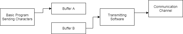
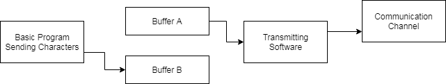
The maximum buffer length, including control characters, can that be received is 512 characters. However, some systems are only configured for 256 characters. For this reason HUNTER will only default to transmitting 200 characters for ease of interfacing.
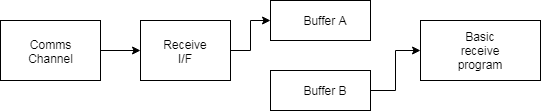
Receive Buffer
As with the transmit buffer arrangement, one buffer is being filled from the communications line while the other is being emptied by the user program.

Data Format
HUNTER is able to accommodate 2780 protocol as both fixed and variable block lengths. Also, 3780 is accommodated.
It is possible to configure the bisync emulator to provide very flexible interfacing for a variety of different host machines.
Standard configurations can be made for:
2780 with variable record length
2780 with fixed record length
3780
The block sizes and record sizes can be adjusted for compatibility and maximum throughput on the communication channel.
Other features which are available for special purposes are:
Intermediate STX
Single record blocks
Space compression
Features not implemented are:
Transparency
Multi drop
All features are discussed in detail later. Although they may all be selected individually, they may not make a compatible protocol. Standard configurations are as follows:
2780 with variable records
(This is the default configuration)
Record length = 80
Block length = 200
Multiple records per block
Record Padding disabled
No intermediate STX
2780 with fixed length records
Record length = 80
Block length = 200
Multiple records per block
Record padding enabled
Intermediate STX enabled
3780
Record length = 80
Block length =512
Multiple records per block
Record padding disabled
No intermediate STX
Space compression is only normally used in 3780 installations.
HUNTER Card Format
Virtually all HUNTER data is delimited by CR (carriage return).
Blocks of data loaded by LINPUT statements are terminated by CR, as are lines of printout. The most straightforward method of block creation is to treat data between CRs as cards of data.
Transmitting Cards
On transmit, if a CR is detected in the data, the communication software will treat it as a record end. The action taken depends upon the amount of room left in the current buffer being prepared for transmission.
For further details on end of record action see :ref:configuring-the-protocol`.
Sending the last Card
To maintain compatibility with existing transmission programs it is essential they should operate without modification. This leaves a problem of how to send the final message buffer if it has not been filled up. If greater than 5 seconds elapses between characters sent from the Basic applications program, then the end of a complete transmission sequence is assured and the current block terminated by ETX CRC. After this has been acknowledged the EOT (end of transmission) is sent to close down the line.
Receiving Cards
The computer generating data for transmission to HUNTER will also block data into records.
To provide application programs with “CR” delimiters, any end of record is converted to CR. The end of record will depend upon the configuration in use. The sequences lUS CRC and IRS will always return CR.
This means that HUNTERS will communicate directly when connected back to back.
BSC receiving stations use ESC sequences for special functions like skipping line. These sequences are ESC n where n can be a number of printable characters. To avoid confusion when these are received HUNTER will ignore received ESCs and their associated following character.
Character Restrictions
HUNTER does not implement any of the transparency features of BSC. It is, therefore, not possible to send any of the following characters:
STX - 02H
ETX - 03H
ETB - 17H
EDT - 04H
SYN - 16H
NAK - 15H
DLE - 10H
US - 1FH
ESC - 1BH
If any of these characters are sent then they may either be lost or cause disruption to the transmission channel.
Configuring the Protocol
For maximum flexibility there are a number of features which may be controlled by the user. These are controlled by a number of flags which are memory locations, listed through this section and also in Memory Locations. All of these locations are preserved after timing set, as with all other communications parameters such as transmission speed.
They may be changed from within a user program using POKE in Basic or direct writing in machine code. Alternatively, the Basic program “SENTSYNC’’ will give a menu of options. A listing is included in section 9.5.
Record Length - (Memory location F853H or 63571)
This is a single byte which defines the maximum record length. It has a range of 1-255, with a default of 80. When outputting data, this length should not be exceeded as there may be insufficient space left in the block to accommodate the record.
If record padding is used, all records are either padded or truncated to fit this length.
Buffer Length - (Memory locations F854-F855, 63572-63573)
This is a two byte number which defines the maximum length of a block. It has a permitted range of 10-512 with a default of 200. The block length must be greater than the selected record length. This control is useful for adjusting the throughput for good or bad telephone lines when transmitting over modems or acoustic couplers. For a good line, the buffer length could be set to maximum so that line turnarounds are kept to a minimum and the maximum data is sent in one block. If, however, the line is a bad one, then if the buffer length is set to a single record length, the amount of data to be re-transmitted in the event of a NAK or data corruption due to the bad line, is kept to a minimum. On Receive, the block length can be anything up to 512 characters. It should be remembered that the block Includes all control characters and record separators.
Single Record Flag - (Memory location F856H or 63574)
This flag controls whether there is single or multiple records in a block. If set to zero (default value) there will be multiple records in each block. If set non-zero, there is only one record transmitted per block.
Record Padding flag - (Memory location F857 or 63575)
This single byte flag is used to control record padding. If this byte is set to non-zero, a record is padded with spaces to its maximum length as defined by record length before being transmitted. On receiving a record, trailing spaces are stripped off. If this flag is set to zero, record padding is inhibited and trailing spaces are not stripped on reception. The default state of this flag is zero.
Record padding is only normally used on fixed length 2780 communications.
Mode flag - (Memory location F858 or 63576)
This flag determines the essential difference between 2780 and 3780. It selects between terminating a record with US (IFH), followed by CRC, or with IRS (lEH) followed by CRC.
2780 mode is the default with the mode flag set to 0. A nonzero flag selects 3780.
2780 mode:
Fixed length records are terminated by any of the following:
Variable length records are terminated by any of the following:
3780 mode:
All records are terminated with:
IRS
On receive, record terminators (CR) are always returned for:
irrespective of the setting of the mode flag.
SIX flag - (Memory location F859 or 63577)
This flag is a single byte and controls the use of intermediate STXs. If the flag is set to non-zero, at the start of every intermediate record an STX is inserted. If the flag is zero, then STXs are not inserted except at the start of the first record in a block. Intermediate STXs are ignored on reception. The default of this flag is zero.
This feature is normally only used in 278O installations.
Retry flag - (Memory location F85A or 63578)
This single byte flag controls how the protocol handles errors. If the flag is set to zero (its default state), then error when an in communication causes the HUNTER to re-try sending the last block, the HUNTER will re-try 10 times before giving a communications error. If, however, the flag is set to non-zero the HUNTER will re-try indefinitely until either it succeeds or the operator switches the HUNTER off.
Space Compression flag - (Memory location F85B or 63579)
This single byte flag controls the operation of space compression. If the byte is set non-zero, any string of more than 2 spaces is compressed into an IGS character and a space count code on transmission. The reverse happens on receive (i.e. the codes are expanded to the string of spaces). If the byte is set to zero (its default state) spaces are not compressed on transmission or expanded on receive.
This feature is not normally used in 2780 installations. It can be used to give increased throughput on a line where there are many spaces.
Addresses of RAM Locations
Name |
Location (Hex) |
Location (Decimal) |
Default Value |
Description |
|---|---|---|---|---|
RECLEN |
F853 |
63571 |
80 |
Record length |
BUFLEN |
F854 |
63572 |
200 |
Buffer length |
SRFLG |
F856 |
63574 |
0 |
Single record flag |
RPFLG |
F857 |
63575 |
0 |
Record padding |
EMFLG |
F858 |
63576 |
0 |
Mode flag |
STXFLG |
F859 |
63577 |
0 |
STX flag |
RETRYS |
F85A |
63578 |
0 |
Retry flag |
SCFLG |
F85B |
63579 |
0 |
Space compression flag |
Note
These flags are preserved during power off and so will remain at their previous setting after subsequent power on.
Synchronous Buffer Organisation
                           Buffer Length

             Record             Record            Record
             Length             Length            Length

-----------------------------------------------------------------------------
|P|    |S| DATA       |  |  | DATA       |  |  | DATA       |  |  |E|C| | | |
|A|SYNS|T| CHARACTERS |  |  | CHARACTERS |  |  | CHARACTERS |  |  |T| R | | |
|D|    |X|            |  |  |            |  |  |            |  |  |B| |C| | |
-----------------------------------------------------------------------------
                                                            IRS
                                                            or EM
                                                            if
                                                            selected

Record Terminator.                        An intermidiate STX,          Line
Depending on the state of the             if selected, would be      turnaround
mode flat, this would be either:          inserted here.             characters
a) an IRS character, or                                              (FFH).
b) an IUS character followed              (Note: If selected
by 2 intermidiate characters.             the STX would not be
                                          counted as part of
                                          the Record).
When calculating the buffer length, space should be included for the characters at the start of the buffer (i.e. PAD, SYNS and STX), the characters at the end (i.e. ETB or ETX, 2 CRC characters and 2 line turnaround characters) and all the required record terminators and intermediate STXs.
Use In Terminal Emulation Mode
Although 2780 work stations are not generally interactive devices, it is possible to use HUNTER in this mode when, for example, testing the system with LOG ON cards, etc.
When in Terminal Emulation any received data is displayed on the screen.
To transmit, a message character may be typed in directly. Provided no mistakes are made, and there is less than 5 seconds between each character, the message is sent on the transmission channel.
Communication Error
There are a number of different line errors which may occur when using this protocol. These are detected and then displayed as communications errors. An error number is also displayed. The meaning of these error numbers is shown in Message Transmission. If use of the ON COMMS statement is made then the error number will be in the COMERR flag.
There is one exception to this rule, see Unanswered Line Bid (Error 01) #unanswered-line-bid. This is the most usual error and will generally be due to a connection fault, as no characters have been received. The option is then given to: Retry transmission ?(Y/N) if ‘Y’ is pressed then HUNTER will send out up to 10 more ENQs (enquiries) and the offer of retry made again. If ‘N’ is pressed then the error O1 is returned, and if programmed through ON COMMS, returns control back to Basic.
Error Messages
Error 01: Unanswered line bid
This is due to not receiving any reply in a request for the line, usually caused by incorrect connection of the communications channel.
Error 02: No response from receiver
After establishing the line, a buffer has been sent to which no response has been given, despite 10 ENQs having been sent.
Error 03; Response not matched by odd-even block count
The wrong positive acknowledgement has been given to a buffer, despite confirmation requests.
Error 04: Retransmission rejected
Repeated transmission of a buffer gets only the NAK response, has tried 10 times.
Error 05: No ENQ after WACK
Having sent out a WACK no acknowledging ENQ has been received for 5 seconds.
Hardware Handshaking
This protocol is generally used with modems or modem simulators. The use of RTS (Request to Send) and CTS (Clear to Send) is therefore specified by the modem, particularly if half duplex or two wire operation is desired (as on the public switched telephone network). Both RTS and CTS may be deactivated as usual.
If they are used, then the following takes place:
If HUNTER is not transmitting then RTS is inactive, allowing the remote modem to transmit.
When starting a transmission buffer the RTS is activated. Before transmission starts CTS is awaited from the modem. When CTS becomes active HUNTER starts transmission.
During transmission RTS is kept active, but CTS is checked, not if it became inactive the transmission would be broken and synchronism dropped.
At the end of the transmission RTS is deactivated and HUNTER awaits reception.
There are no timeouts on the handshakes.
Hardware Configuration
The transmission channel could be the switched public network, 4 wire private lines etc.
The two modems and the channel could be a modem eliminator for nearby operation.
As can be seen the modems generally create all the clocking in this simple arrangement. HUNTER will not generate any actual clocking of its own, except when self synchronising to the data.
The handshake signals RTS and CTS ensure correct data flow over a half duplex line (allowing the modems to settle etc.) They may not be necessary over 4 wire links.
HUNTER To HUNTER Connection
To operate this protocol back-to-back between two HUNTER’S it is only necessary to use a crossed 3 wire lead (TX,RX and ground). If the handshake lines are connected, then CTS must be deselected on the menu as the handshaking is only configured for modem operation.
HUNTER’S need to be set for self clocking at the designed speed, typically 1200 baud or 300 baud over slow speed async modems.